Research → Mechatronic systems → Pneumatically actuated ball and beam system → Model of the ball and beam system
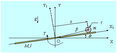
Consider the ball and beam system shown in figure below, where a fixed coordinate system (OXY) is attached to the center of rotation of the beam. It is supposed that the center of gravity of the ball intersects the axis of rotation of the beam.

Schematic drawing of ball and beam system
The ball is in general a distance x measured in meters from the pivot point O, and the beam is rotated at an angle q measured in radians by applying a torque T at the pneumatic motor.
The Euler-Lagrange method given by:

was used to derive the equations of motion for the system with two generalized coordinates:
 - ball position coordinate
 - beam angle coordinate
and only one applied torque.
The expressions for the kinetic energy, K, and potential energy, P, for the beam are given by:


where we used  as the rotational inertia
of the beam about the center of rotation. It is assumed that the beam
stores no potentional energy.
Thus, the expressions for the kinetic energy, K, and potential energy,P, for the ball are given by:


where  is the ball's moment of inertia.
Applying the Lagrange equations of motion to the system with the two generalized coordinate x and q, and if viscous friction is included in the model, the following nonlinear mathematical model of the system is obtained:

or written in the matrix form:

The linearized equations of motion (about the equilibrium point assuming:
 ,
,
 ,
,
 )
can be written. With the assumption that: all friction in the system
is negligible, the ballís mass is negligible small in comparison with
the beamís mass, the change in potential energy of the ball during the
system operation is negligible, a following simplifying mathematical
model of the system is obtained:

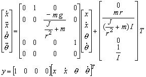
The linearized system equations written in the state-space form are as follows:

The symbols and model parameters in above equations used for simulation and
controller design procedure are listed in below table.
Numerical values of physical system parameters
|
Symbol |
Parameter |
Value |
|
m |
Mass
of the ball |
0.12
kg |
|
M |
Mass
of the beam |
0.45
kg |
|
r |
Roll
radius of the metal ball |
0.015
m |
|
l |
Length
of the beam |
0.8
m |
|
J |
Moment
of inertia of the ball 2/5 m r2 |
1.08
e-5 kgm2 |
|
I |
Rotational
inertia of the beam Ml2/12 |
0.024
kgm2 |
|
g |
Acceleration
due to gravity |
9.81
ms-2 |