Research → Mechatronic systems → Inverted pendulum driven by pneumatics → Model of the inverted pendulum system
Nonlinear mathematical model of the dynamics of the inverted pendulum is given by:
![]()
![]()
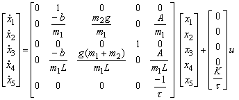
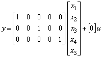
Below is given the state space description of a linearized system, including dynamics of pressure changes in the pneumatic cylinder. The linearization is obtained near the equilibrium point, assuming:
![]()


System states are:
![]()
In the above mathematical model the dynamics of pneumatics is simplified, and given as a first-order lag system. Here, the input is voltage signal u (0-10 V) on the solenoid of the pneumatic valve, and the output is a pressure difference Δp between two chambers of the rodless pneumatic cylinder:
![]()
where τ is a time constant (0.12 s), and K is a gain (0.11 MPa/V). These parameters were experimentally determined from transient responses.
The symbols and numerical values of physical system parameters in above equations are as follows:
|
A – area of the piston, 0.00018 m2 |