Research → Mechatronic systems → Pneumatically driven inverted wedge → Model of the inverted wedge system
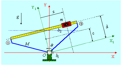
Consider the inverted wedge system shown in below figure, where a fixed world coordinate system (OXY) is attached to the base of the wedge.

Several simplifying assumption were made in developing a dynamical model such as: rigid links, two degrees of freedom, viscous friction in the cylinder and at the frame revolute part.
The Euler-Lagrange method given by:
![]()
was used to derive the equations of motion for the system. The generalized coordinates for the considered system are:
![]()
For modeling purposes, we first divide the inverted wedge system into two subsystems: first which includes the frame with the cylinder and without the slider (denoted with the index 1), and second, which includes the slider only (denoted with the index 2). The expressions for the kinetic energy, K, and potential energy, P, for the system are:

Applying the Lagrange equations to the system with the two generalized coordinate θ and x, where viscous friction is included in model, the following nonlinear mathematical model of the system is obtained:

The linearized equations of motion (about the equilibrium point assuming:
![]()
written in the state space form are as follows:

The symbols and model parameters in above equations are listed in below table.
Numerical values of physical system parameters
|
Symbol |
Parameter |
Value |
|
m |
Mass of slider |
0.25 kg |
|
M |
Mass of frame (+ cylinder; - slider) |
1.3 kg |
|
c |
Distance from center of gravity of frame to point of rotation |
0.03 m |
|
d |
Distance from sliding surface to point of rotation |
0.062 m |
|
b1 |
Viscous friction coefficient of frame |
0.05 Nms |
|
b2 |
Viscous friction coefficient of slider |
45 Ns/m |
|
g |
Acceleration due to gravity |
9.81 ms-2 |