Battery/ultracapacitor experimental setup
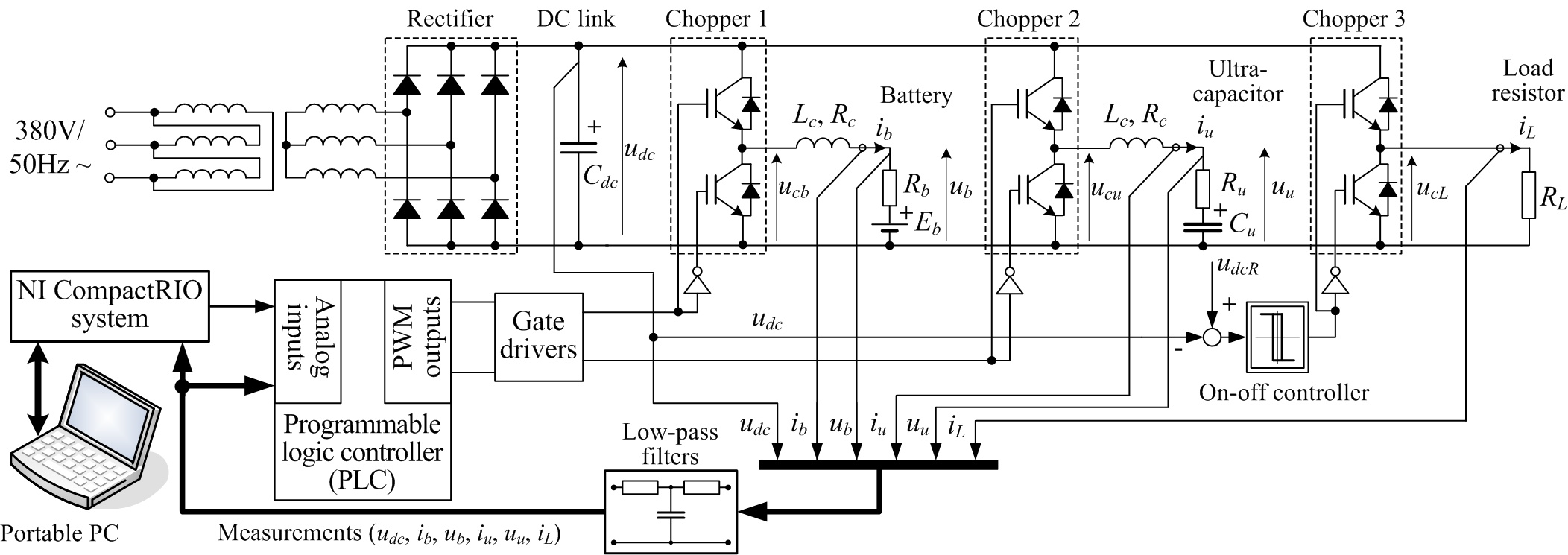
The battery/ultracapacitor experimental setup (Fig. 1a) has been developed for the purpose of experimental characterization and modeling of battery and ultracapacitor-based energy storage systems, such as those used in renewable energy systems (RES), or hybrid electric and battery electric vehicle (HEV/BEV) applications. The developed battery/ultracapacitor models can then be used as a basis for the development of appropriate battery state-of-charge (SoC) and state-of-health (SoH) estimators, and charging/discharging controllers aimed towards battery life and energy efficiency enhancement.
The setup comprises three two-quadrant IGBT-based back-boost DC/DC power converters with PWM switching frequencies configurable up to 5 kHz. The power converter components are rated for 50 A continuous current (75 A peak current), and the rectifier/DC link is designed for 40 V DC rated voltage, thus accommodating for approximately 2 kW continuous power for each buck-boost converter. The battery and ultracapacitor chopper are able to operate both in the buck (step-down) and boost (step-up) mode, thus facilitating controlled continuous-current battery/ultracapacitor charging and discharging. The third chopper is used for DC link voltage control during battery/ultracapacitor discharging operation by means of power dissipation at the external load resistor bank comprising six 2.2Ω/200W resistors connected in parallel (overall load resistance RL = 0.367 Ω). Fig. 1b shows the photograph of the power converter cabinet, which includes the ultracapacitor module and the low-level control hardware, i.e. programmable logic controller (PLC) and IGBT PWM drivers.
The setup is suitable for testing standard starting-lighting-ignition (SLI) automotive batteries, as well as advanced battery designs, such as state-of-the-art LiFePO4 cells (either individually or in stacks). Individual buck-boost converters are controlled by dedicated PI current controllers (low-level controllers) implemented in programmable logic controller (PLC), while the high-level control/guidance, supervision and estimation algorithms are implemented in National Instruments (NI-LabView) software environment, which is running on the standalone NI control hardware platform (NI Compact RIO), monitored by a master PC.
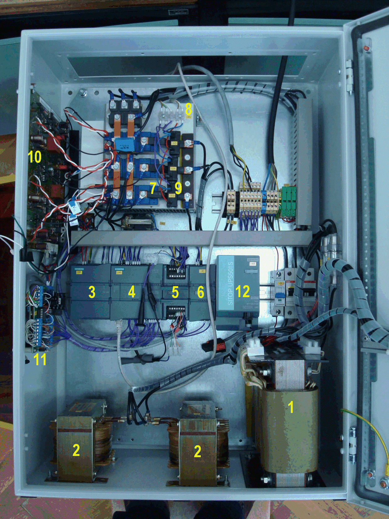
Legend:
1 → Three phase transformer
2 → Inductors (chokes)
3 → PLC power supply
4 → PLC CPU unit
5 → PLC analog input module
6 → PLC analog output module
7 → IGBT switches
8 → Heat-sink
9 → Current sensors
10 → IGBT PWM drivers
11 → Safety logic circuitry
12 → Ultracapacitor (5 kJ, 24 V)
Fig. 1. Battery/ultracapacitor setup: principal electric schematic (a) and photograph (b).
Publications
-
Energy conversion and management, Vol. 114, pp. 154-167, 2016. -
Development of Smart Charging and Energy Management Controls for Batteries and Ultracapacitors
In Proc. of NIDays 2014 Conference, Zagreb, Croatia, 2014. -
A Design of DC Bus Control System for EVs Based on Battery/Ultracapacitor Hybrid Energy Storage
IEEE International Electrical Vehicle Conference (IEVC 2014), Florence, Italy, 2014. -
Battery/Ultracapacitor Test Setup Control System Design and Verification
Proceedings of IEEE Eurocon 2013, pp. 1050-1057, Zagreb, Croatia, 2013. -
Battery/Ultracapacitor Test Setup Design
In Proc. of NIDays 2013 Conference, Zagreb, Croatia, 2013.