Control of Pneumatics Servo Systems
Pneumatically actuated drives have been used in widespread applications of different automation systems owing to their advantages such as: low-cost, high power-to-size ratio, cleanliness, easy of maintenance, simple working mechanism, high speed action capabilities and many more. Over the years, pneumatic drives are used in industrial automation for pick-and-place positioning problems using simple on-off directional valves. The motion traveled was limited by the actuator stroke length or restricted by fixed mechanical stops or proximity sensors. Therefore, for flexible positioning tasks some other motion technologies based on costly electric or hydraulic systems are normally used. Development of the proportional control pneumatic valves in the late 1980's and the ready availability of low-cost microprocessors, lead to new applications of pneumatics, beyond its traditional use. In recent years, investigations have been made for employing pneumatic drives to accomplish more sophisticated position control or tracking performance. The objective is to develop the pneumatic systems with the process performance equivalent to that achievable with electric and hydraulic systems.
However, there are several reasons why the possibility of servo-applications of pneumatic drives is limited in practice. The nonlinear effects of pneumatic systems caused by the phenomena associated with air compressibility, significant friction effects, load variations, etc., make accurate position control of a pneumatic actuator difficult to achieve. It is very challenging task to get an accurate mathematical model for describing pneumatic servo drive behavior. In order to meet desired requirements of the controlled system, increased attention in research community is being paid to development of pneumatic equipment, as well as to the improvement of control strategies.
In the Laboratory of Automation and Robotics at the Faculty of Mechanical Engineering and Naval Architecture, University of Zagreb, an experimental system has been made in order to study different control methodologies for pneumatic servo drives. The photo of the laboratory equipment and the schematic description of the control system are illustrated in Figure.
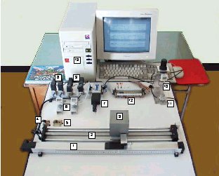
- 1. Linear potentiometer - FESTO MLO-POT-500-TLF
- 2. Pneumatic rodless cylinder - SMC CDY1S15H-500
- 3. Load mass
- 4. Rotational potentiometer
- 5. Ref. voltage on potentiometer
- 6. Pressure sensor - SMC ISE4-01-26
- 7. Proportional valve (servovalve) - FESTO MPYE-5 1/8 HF
- 8. Proportional pressure valves - SMC VY1A00-M5
- 9. On/off solenoid valves - SMC EVT307-5D0-01F
- 10. Filter-regulator unit
- 11. Air supply valve
- 12. Electronic interface
- 13. Control computer
In order to analyze and compare the usefulness of control structures of position control system, several conventional control strategies and also strategies based on fuzzy logic controller have been considered. Main research has been made with relatively costly proportional directional control valve (FESTO MPYE-5 1/8 HF-010B).
Below figures illustrate the experimental results for position control of pneumatic servo drive using PID controller tuned according to damping optimum, which includes a friction compensation algorithm.
For the sake of developing a cheaper pneumatic servo drive solution we have been implemented also two proportional pressure valves (SMC VY1A00-M5), and two on/off solenoid valves (SMC EVT307-5D0-01F). This way, a new level of price/performance control system is achieved using appropriate control techniques.
Based on the existing laboratory equipment of pneumatic servo system with different types of pneumatic proportional and on/off valves some others mechatronic systems have been realized, that are used in education and research.