Electronic throttle
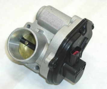
The experimental setup consists of the electronic throttle body (ETB), a motor driving unit (a chopper), and a control computer (see photo below). The ETB is a DC drive which provides precise positioning of the throttle plate. The throttle plate position is measured by means of an embedded potentiometer. The DC motor is supplied from the chopper, which is connected to a standard car battery. The control computer acquires the actual throttle position signal, executes the control algorithm, and commands an analogue signal of required motor armature voltage to the chopper.
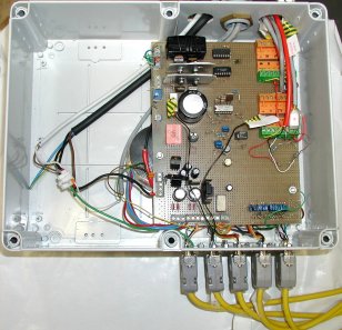
The chopper consists of an H-bridge power electronics circuit, an analogue PWM driver, a current sensor, a watchdog timer, and a measured-signals low-pass filter bank. The chopper is designed by the firm NEV-EL, Zagreb, Croatia, upon our specifications. The H-bridge utilizes individual power MOSFETs and has similar characteristics (internal resistance, maximum and rated currents) as standard integrated automotive H-bridge drivers. The switching frequency of the H-bridge is f ch= 4 kHz. The PWM driver changes the H-bridge duty-cycle based on the commanded voltage from the control computer. The armature current sensor is included in the present chopper to facilitate some offline identification experiments and motor overload detection. Also, it can be used for the possible design of an inner current control loop-based control system. The watchdog timer is used to prevent ETB damage in the case of possible control computer hardware or software failure. All the measured signals (throttle position, armature current, battery voltage, and potentiometer reference voltage) are filtered using analog low-pass filters with the cutoff frequency fc = 1kHz.
The control computer is a standard PC equipped with an analog/digital input/output data acquisition card. This card comprises 16 single-ended, bipolar, 12-bit analog input channels (±10V), and 2 unipolar, 12-bit analog outputs (0-10V).
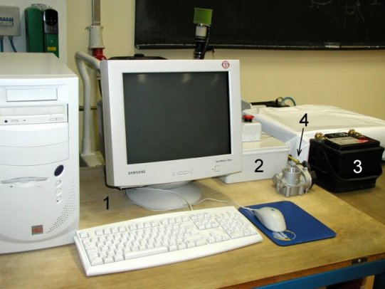
Fig. 1. Experimental setup of electronic throttle.
Publications
-
Lambert Academic Publishing, Saarbrücken, 2011. -
Adaptive Control of Automotive Electronic Throttle
Control Engineering Practice, Vol. 14, pp. 121-136, 2006.