Magnetorheorological fluid clutch (MRF clutch)
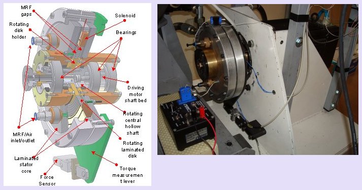
An experimental magnetorheological fluid (MRF) clutch has been developed in order to support clutch modeling and control research. The clutch (or brake) is of a plate design, as shown in the figure below. By varying the solenoid dc current, the rheological properties of fluid that suspends micro-size steel particles are changed, thus changing the braking torque on the clutch disk.
The clutch is designed for a convenient direct mounting on an existing electrical servomotor of the SI engine experimental setup (no coupling and external bearing are used). Rotating parts carrying the clutch disk are connected to the central hollow shaft. The clutch case stays fixed to the setup base through the lever-based torque measuring system. The clutch case and the rotating disk holder are built of non-magnetic materials (aluminum and brass, respectively). The MRF gap can be adjusted by switching the rotating disks of different widths. For this purpose, only one column of the magnetic core is removed, while other parts including the solenoid remain attached to the motor.
MRF containment around the rotating disk and inside the central hollow shaft is sealed to prevent the MRF leakage. Static seals are of the "O" ring PTFE type, and rotary dynamic seals are of a simmering type. Use of permanent-magnet seals is also possible. In the case of disk change or when various dynamic seals are tested, the MRF need to be sucked out the clutch and then refilled. An external MRF tank with a pumping mechanism is used to facilitate MRF handling.
The magnetic core is laminated using the isolated ferromagnetic slots of approximately 3 mm width, in order to reduce the eddy current effect on the torque response speed. For the same reason, the ring-shape slots (see the rotating disk and the related stator slots) are cut in radial direction. Tiny thermocouple and magnetic flux sensors are mounted in the side slot nearby the MRF gap. PTC temperature sensor is inserted into the solenoid bed.
An electrical servo-motor of permanent-magnet synchronous type is used to drive the clutch. The maximum speed and torque are 4000 rpm and 28 Nm, respectively. The motor is typically used in the closed-loop speed control mode (10 Hz bandwidth), but open-loop torque control (80 Hz bandwidth) can also be used in some experiments (e.g. breakaway experiment). The motor position measurement resolution is 0.09°.
The solenoid is supplied from a four-quadrant 24V/50A MOSFET chopper. The chopper is connected to a 24 V automotive battery, and it comprises a fast Hall effect current sensor. The measured current signal is fed back to a Pentium III industrial computer that controls the chopper. The same computer controls the frequency converter that supplies the driving servomotor. The control computer is equipped with analog input/output and encoder data acquisition cards. The control code is written in C with the sampling time of 1 ms.
Publications
SAE paper #2009-01-0142, 2009 SAE World Congress, Detroit, MI, 2009.