E-clutch test rig
E-clutch, also known as clutch-by-wire, is a type of semi-automated dry clutch used within manual transmissions (or a fully automated clutch utilized within electrified transmissions). A position sensor placed on the clutch pedal provides a driver intention signal to the control system, which then operates the clutch via an actuation system. Consequently, the driver maintains its existing driving habits, while the control system allows for fuel savings and compensates for possible poor reaction by the driver (e.g. avoiding engine stalling). Development of precise E-clutch control system necessitates experimental characterization and verification by means of a purpose-built test rig.
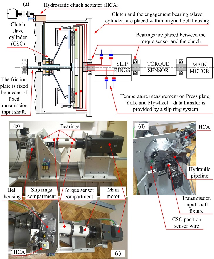
The developed E-clutch test rig is driven by a permanent-magnet synchronous servomotor with the rated power, speed and torque of 35 kW, 3000 rpm, and 110 Nm, respectively. The motor can develop the torque of 230 Nm for 1 min and 270 Nm for 3 s. The speed and position are sensed by using a precise encoder built in the servomotor. The motor power is transmitted to the clutch dual-mass flywheel (DMF) via a telemetric torque sensor (model T22 by HBM, measurement range up to 500 Nm). In order to obtain accurate clutch torque signal, the torque sensor signal is compensated for the acceleration torque and clutch bearing friction. The clutch friction plate is locked by fixing the transmission input shaft. The hydrostatic-type clutch actuator and the clutch release bearing are mounted in the same way as on real transmission. The test rig arrangement allows for future upgrades towards an E-clutch transmission/drivetrain rig including an option of installing a dynamometer.
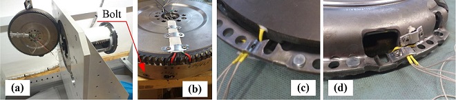
The clutch is equipped with five temperature sensors. Three of them are installed in the bores manufactured in the primary and secondary flywheel discs and the pressure plate (PT100 probes by Honeywell, model HEL707-T-0-12-00). All sensors are positioned at the mean radius of respective component and at 4 mm axial distance from friction contact plane. The fourth temperature sensor is placed in a groove cut on the surface of the yoke, while the fifth one is placed on the top surface of the bell housing at the minimum distance from the friction plane. The signals from the temperature sensors installed on the rotating components are transferred to the data acquisition system via a data slip ring system (SK5 model by HBM). Three axial bores were made through the primary disc outer shell for temperature sensors' wire guidance, while the primary and secondary discs were fixed together by means of six radially placed bolts. The DMF function related to torsional vibration dampening is disabled in this way, but this feature is not relevant for the rig as it is driven by the electric servomotor. Other characteristics of the DMF including its inertia, thermal masses and heat transfer remain unchanged.
The test rig measurement and control subsystem is built around an industrial Pentium III PC, and the control software is written in the C programming language for DOS operating system. The acquired data include the aforementioned measurements, as well the hydrostatic actuator sensor readings such as master and slave cylinder positions and fluid pressure.
Publications
-
Transactions of FAMENA, Vol. 48, No. 3, pp. 21-35, 2024. -
Design of a Test Rig in Support of E-clutch Dynamics Characterisation, Modelling, and Control
International Journal of Powertrains, Vol. 9, No. 3, pp. 221–239, 2020. -
E-clutch Torque Control Including Compensation of Thermal Expansion Effects
IEEE Transactions on Vehicular Technology, Vol. 69, No. 1, pp. 246–257, 2020. -
Design of a Test Rig in Support of E-clutch Dynamics Characterization, Modelling, and Control
Powertrain Modelling and Control Conference (PMC 2018), Loughborough, UK, 2018.