Research → Mechatronic systems → Pneumatically actuated ball and beam system
The ball and beam system, as a classic control object, is one of the most popular laboratory systems for teaching control
systems techniques and for testing control algorithms. This system is typical of the dynamics that are found in many of
the challenging applications of modern control and is often used as a benchmark problem to help explain control of
unstable, nonlinear and speed system. Its complete mathematical model is quite complicated, the system itself is open
loop unstable, and has strong nonlinearities and uncertainties. However, it is also very simple to understand how the
system works and it can be studied many conventional and modern design approaches. It is an under-actuated mechanical
system in which the dimension of degrees-of-freedom exceeds the dimension of the control input variables. The system
has one control input, which is the torque proportional to the pressure difference between two chambers of rotary
actuator. There are two measured outputs, which are the beam angle q and the ball position
x.
In this balancing mechanism, the purpose of the system design is to automatically regulate the position of the ball
along the beam by manipulating the angular position of the beam, which is realized by pneumatic rotary drive. Energy
of compressed air can move the beam attached to the pneumatic motor left and right in order to keep the ball in a
desired position. The controlled system should have zero steady state error in position of the ball and satisfactory
disturbance rejection properties.
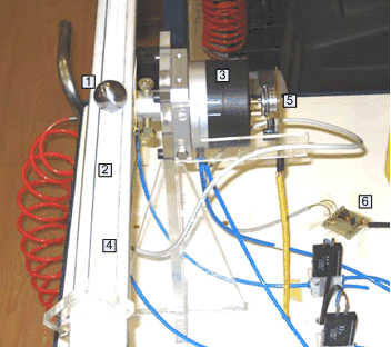
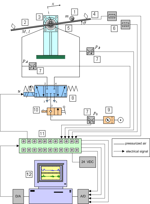
Below figures illustrate the photo of the experimental setup (see experimental
system description) and the schematic diagram of the pneumatically actuated
ball and beam system.
|


