Experimental electrical vehicle
The experimental electrical vehicle with an in-wheel motor (see the photograph below and the video about our research activities broadcasted by Croatian television in the "Znanstvena petica" television show) has been developed in support of research of modeling, estimation, and TCS/ABS control of tire-road friction dynamics. The vehicle comprises three standard car wheels, with the investigated driven wheel mounted at the vehicle front, and the other two (non-driven) wheels mounted on the rear axle.
The vehicle mechanical system can be divided into several assemblies: main frame (1) with hood (7), front wheel assembly with in-wheel electrical servomotor (2,3), rear wheel assembly (4), redundant wheel assembly (5), in-wheel motor cooling system (6), and an emergency braking system. The in-wheel motor is based on a built-in torque motor of permanent-magnet synchronous type (8). It transfers the torque directly to the wheel, with the maximum torque of 880 Nm and the torque response time of 2 milliseconds. The motor is equipped with a precise incremental encoder that generates 2 million pulses per revolution after electronic interpolation. The in-wheel motor is also used as the main braking device. The rear wheels are equipped with drum brakes that are activated by an electromagnet in power failure or emergency situations. For the purpose of vehicle velocity and acceleration measurement, the right rear wheel comprises the precise incremental encoder. For experiments where the rear wheels are being braked (e.g. during up-hill driving emulation), the vehicle speed and acceleration can be measured by using the redundant wheel. When steered by a fixed angle (e.g. 20 deg), the redundant wheel equipped by a lateral force sensor can also be used to measure tire-road friction coefficient.
The vehicle electrical system (see the principal schematic below) can be divided into the electrical drive and power supply system, and the vehicle control system. The main parts of the electrical drive and power supply system are: the servomotor (5) with the frequency converter (8), the coolant fluid pump (9), rear brake electromagnet (19), and power supply box (22). The core of the vehicle control system is the industrial PC with Pentium III processor (14) equipped with appropriate plug-in cards for signal acquisition (e.g. from incremental encoders (6, 7) and temperature sensors (11-14)), the programmable logical controller (PLC) (25) and the command console (26). The operator commands the vehicle via the command console. The operator's command and the return information are transmitted via serial communication by means of information lines integrated into the power supply cable, and are processed by the PLC. The on-vehicle industrial computer is also equipped with a WLAN communication card for the purpose of wireless communication between the on-vehicle computer and the operator's portable PC computer (27), which is used for control program upload and recorded data download.

Fig. 1. Photograph of experimental electrical vehicle with in-wheel servomotor.
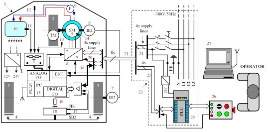
Fig. 2. Principal scheme of the vehicle electrical system.
Video 1. Short video presentation of the experimental electrical vehicle.
Publications
-
Doctoral thesis (in Croatian), Faculty of Mechanical Engineering and Naval Architecture, University of Zagreb, Croatia, 2010. -
Experimental Identification and Modeling of Dynamic Tire Friction Potential on Slippery Surfaces
XIX IAVSD Symposium, Berkeley, CA, 2007. -
Experimental Identification of Dynamic Tire Friction Potential on Ice Surfaces
XIX IAVSD Symposium, Milan, Italy, Aug/Sep 2005; Aug/Sep 2005; Vehicle System Dynamics, Vol. 44, Supplement 1, pp. 93-103, 2006. -
An Experimental Electrical Vehicle with In-wheel Motor
CD Proc. of 13th Int. Conference on Electrical Drives and Power Electronics (EDPE 2005), Dubrovnik, Croatia, 2005.