Inertial sensors test rig
An experimental setup for inertial sensors characterization (see the below photograph) has been developed as a part of research activities on estimation of vehicle dynamics state variables. By using this setup, the effects of measurement offset, noise, drift, and nonlinearity on the measurement/estimation accuracy can be investigated under laboratory conditions.
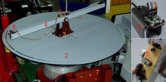
The test rig consists of a torque servo-motor mounted on the rig frame, and a metal disc plate or a beam that carries the tested sensors and are connected directly on the motor shaft. The torque servo-motor with related control hardware is adopted from the experimental electrical vehicle. It provides accurate closed-loop control of the angular speed and angle.
The rig supports two basic testing configurations: (i) a beam configuration for characterization of gravity influence on sensing accuracy (related to e.g. road bank and roll effects) and (ii) disc plate configuration for characterization of placement-related measurement errors (e.g. axis misalignment errors) and testing a yaw rate estimator based on two accelerometers. The gyroscope sensor is placed in the center of rotational axis of the test rig, while the accelerometers are mounted on the disc plate or on the beam ends, equidistantly from the rotational axis.
The test rig provides comparative performance analysis of different types of inertial sensors, such as low-cost automotive inertial sensors (e.g. Analog Devices biaxial accelerometers ADXL203 and single-axis gyroscope ADXRS150) and more expensive inertial sensors (e.g. yaw rate sensor DRS-MM1.0R from Bosch or precise capacitive accelerometer 3801D1FB20G from PCB).