Pin-on-disc tribometer
The pin-on-disc-type CNC tribometer has been developed for the purpose of conducting static and dynamic friction coefficient tests over a wide range of operating parameters and different friction materials.
In the given dry dual clutch friction application, the pin sample (1) is formed by cutting out a 20x20x4 mm piece of the clutch friction plate. The sample is placed within a holder (2), which connects the sample with the three-axial piezoelectric force sensor by Kistler (3) that measures normal force and two horizontal plane forces. The holder is made from a thermal insulating material in order to prevent a significant heat flux from reaching the force sensor. The sample and force sensor temperatures are measured by thermocouples (4).
The sample and force sensor fixture can move in the vertical direction, driven by a screw-drive electrical servo-motor module (5). The vertical-axis motion is controlled by a vertical force regulator to accurately adjust the sample normal force. In order to suppress the normal force oscillations caused by disc surface unevenness, a system of leaf springs (6) is placed between the sample and force sensor assembly and the screw-drive axis.
The test disc (7) is made by cutting an appropriate size from the previously disassembled clutch press plate, and attached to a rotating table (8) which incorporates an electrical heater. In combination with the PT probe temperature sensor (9) inserted into the disc, fast and accurate heating of the attached test disc is enabled. A thermal insulation disc (10) is placed between the table and a table carrier (11) to prevent/minimize the heating of the rest of rotational axis. The table is driven by an electrical servomotor (12) through a belt gear (13), which is controlled by a speed regulator to precisely adjust the pin-disc slip speed. A precise encoder (14) is mounted at the rotating table shaft for direct slip speed sensing.
Two separate slip ring systems are installed: a power slip ring (15) which connects the heater in the rotating table to the power converter, and a data slip ring (16) by HBM which connects the PT probe to the temperature control system. Thus, it is possible to precisely control the disc temperature during the entire test.
Air conditioning system (17) is attached to the tribometer chamber in order to enable experiments at low temperatures, and extension of experiment duration at high temperatures.
The tribometer also includes a direct linear servodrive system (18), which in an alternative tribometer configuration provides precise linear motion of the table in a wide velocity range (for the same vertical axis containing the friction sample).
The control and monitoring system is built around an industrial PC (19).
Tribometer Operational Parameters:
- 1) Normal force range: 6 to 100 N or 6 to 1000 N (depending on the chosen force sensor amplifier range, influences measuring precision)
- 2) Rotational axis max speed: 6000 rpm
- 3) Rotational axis motor power
- Natural cooling: 1.3 kW (2.1 Nm)
- Water cooling: 6.2 kW (9.8 Nm) - 4) Belt gear possible transfer ratios: 1:1 or 1:3
- 5) Linear axis max slip speed: 2 m/s
- 6) Linear axis max acceleration: 56 m/s2
- 7) Temperature range: 0 to 250°C
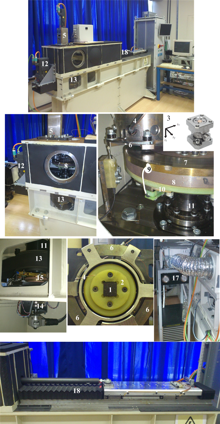
1 – Friction sample
2 – Sample holder
3 – Tri-axial piezoelectric force sensor
4 – Thermocouple wires
5 – Screw-drive servo motor
6 – Leaf springs
7 – Test disc
8 – Rotating table
9 – PT probe
10 – Thermal insulation disc
11 – Table support
12 – Table drive servo motor
13 – Belt drive
14 – Rotating table encoder
15 – Power slip ring
16 – Data slip ring
17 – Air conditioning system
18 – Linear servo motor
19 – Industrial PC
Publications
-
Kupplungen und Kupplungssysteme in Antrieben 2019, Ettlingen bei Karlsruhe, Germany, 2019. -
Design of a Pin-on-disc-type CNC Tribometer Including an Automotive Dry Clutch Application
Mechatronics, Vol. 40, pp. 220-232, 2016. -
Experimental Characterization and Modeling of Dry Dual Clutch Wear
SAE paper #2014-01-1773, SAE International Journal of Passenger Cars - Mechanical Systems, Vol. 7, No. 1, pp. 326-337, 2014. -
Design of Normal Force Control System for a Pin-on-Disk Tribometer including Active and Passive Suppression of Vertical Vibrations
Automatika , Vol. 54, No. 3, pp. 364-375, 2013. -
Experimental Characterization and Modeling of Dry Dual Clutch Thermal Expansion Effects
SAE paper #2013-01-0818, SAE International Journal of Passenger Cars - Mechanical Systems, Vol. 6, No. 2, pp. 775-785, 2013. -
Normal Force Control for a Pin-On-Disk Tribometer Including Active or Passive Suppression of Vertical Vibrations
Proceedings of 2012 IEEE Multi-Conference on Systems and Control (2012 IEEE MSC), pp. 488-493, Dubrovnik, Croatia, 2012. -
Experimental Identification and Modeling of Dynamic Tire Friction Potential on Slippery Surfaces
XIX IAVSD Symposium, Berkeley, CA, 2007. -
Experimental Identification of Dynamic Tire Friction Potential on Ice Surfaces
XIX IAVSD Symposium, Milan, Italy, Aug/Sep 2005; Aug/Sep 2005; Vehicle System Dynamics, Vol. 44, Supplement 1, pp. 93-103, 2006.