Modeling of Active Differential Wet Clutch
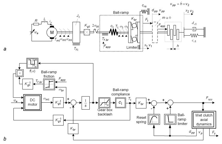
Modeling of active differential clutch is a key step toward modeling of active differential drivelines and development of clutch/differential control strategies. Fig. 1a shows the structure of clutch system for the particular active limited slip differential. The multi-plate wet clutch is actuated by a geared dc motor and a ball-ramp mechanism. A reset spring is utilized to open the clutch in the case of power supply failure, where the mechanism motion in the reverse direction is constrained by a mechanical limiter.
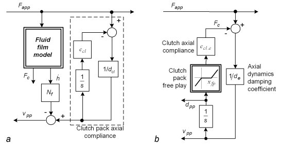
Fig. 1b shows the block diagram of clutch axial force development model. The dc motor dynamics model is of a standard form extended with motor+gear friction and motor thermal dynamics. The gear backlash is modeled by a dead-zone element. The ball-ramp mechanism model includes a nonlinear compliance curve and a Dahl submodel for clutch axial force-dependent friction. The friction submodel also describes friction in ball-ramp mechanism axial and radial bearings. The reset spring is described by a nonlinear compliance curve, while the ball-ramp limiter curve has "infinite" stiffness for reverse motion below the limited position and zero stiffness for forward motion. The first-principle wet clutch axial dynamics model describes the fluid film squeeze dynamics and the clutch axial compliance (Fig. 2a). Since the resistive fluid-squeeze force has been found to be much lower than the large applied force (up to 40 kN), the clutch axial dynamics model is simply described by a free play (backlash) dead-zone element and an equivalent axial damping coefficient (Fig. 2b). The parameters of the model in Fig. 1 have been determined by a step-by-step experimental identification procedure.
The clutch axial force Fapp (output of the model in Fig. 1) is fed to the clutch friction model together with the clutch slip speed ωs and the clutch friction interface temperature ϑ. The clutch friction model is of reset integrator type with a modification related to variable normal force. The Coulomb friction torque is calculated from the known clutch effective radius, the normal force Fapp, and the friction coefficient μ. The friction coefficient is mapped with respect to slip speed, normal force, and temperature, as shown in Fig. 3a. The clutch temperature ϑ is obtained from a first-order nonlinear model based on the heat balance equation. The core of this thermal model is the heat transfer coefficient map (Fig. 3b), which is fed by the slip speed and normal force signals. The heat transfer coefficient description also includes experimentally identified pure delay+lag dynamics for an improved modeling accuracy illustrated in Fig. 4.
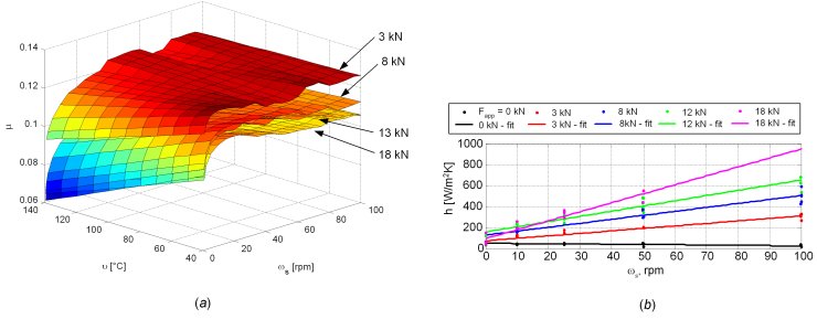
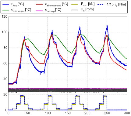
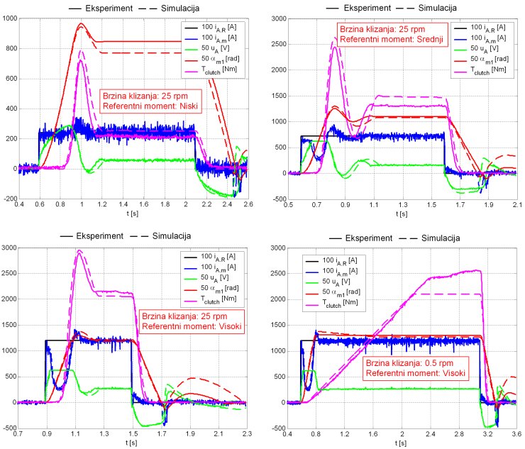
Fig. 5 shows the experimental validation results of the overall clutch model with respect to stepwise test signal of dc motor current reference. The model accurately captures the highly nonlinear clutch dynamics characterized by the initial pure delay due to the clutch free play, transient response with overshoot due to the ball-ramp friction and compliance effects, relatively fast clutch-opening response with "bouncing" around the limiting position, and slow response at low slip speeds due to the structural compliance of connecting shafts (halfshafts).
More details on the model structure, identification, and validation can be found in our publications listed below.
Publications
-
Encyclopedia of Automotive Engineering, pp. 1-19, John Wiley & Sons Ltd., 2014. -
Bond Graph Modeling of Automotive Transmissions and Drivelines
Proc. of 7th Vienna International Conference on Mathematical Modelling (MATHMOD), Vienna, Austria, 2012. -
Modelling of Electromechanically Actuated Active Differential Wet Clutch
Proceedings of the Institution of Mechanical Engineers, Part D: Journal of Automobile Engineering, Vol. 226, No. 4, pp. 433-456, 2012. -
Modeling and Control of Vehicle Powertrain Components with Emphasized Friction Effects [open access]
Doctoral thesis (in Croatian), Faculty of Mechanical Engineering and Naval Architecture, University of Zagreb, Croatia, 2010. -
Experimental Characterization of Wet Clutch Friction Behaviors Including Thermal Dynamics
SAE paper #2009-01-1360, SAE International Journal of Engines, Vol. 2, No. 1, pp. 1211-1220, 2009. -
Modeling and Experimental Validation of Active Limited Slip Differential Clutch Dynamics
DVD Proc. of 2008 ASME International Mechanical Engineering Congress and Exposition (IMECE 2008), Boston, MA, 2008.