Traction Control/ABS
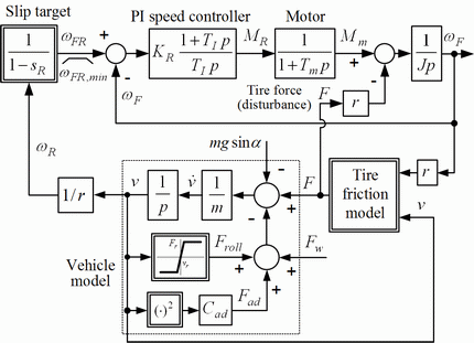
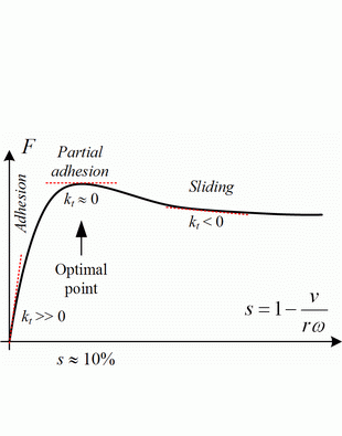
Traction control systems (TCS) and anti-lock braking systems (ABS) keep the longitudinal tire force close to its peak value, thus maximizing the vehicle acceleration (TCS) or deceleration (ABS), while providing a good lateral tire force reserve for cornering. TCS systems are usually implemented by means of driven wheel speed ωF control (Fig. 1), with the wheel speed target ωFR calculated based on the vehicle velocity measurement and the target wheel slip sR for maximum longitudinal tire force (typically sR = 10%, see Fig. 2). The vehicle velocity is directly reconstructed from the non-driven wheel speed ωR in the case of a 2WD vehicle.
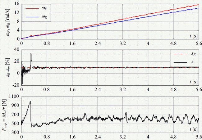
The traditional TCS strategy has been verified by utilizing the University's experimental electrical vehicle for the case of driving in an ice arena. Fig. 3 shows the experimental responses of the traditional (slip-based) traction control system with the constant slip target sR = 10%. These responses show that wheel slip is accurately kept at the target value. The slip perturbation magnitude is typically less than 0.5%. The slip excursions are effectively suppressed by the driven wheel speed controller. Namely, it takes only 50 ms to bring the slip back to the desired slip value after a sudden wheel slip change has occurred during vehicle launch.
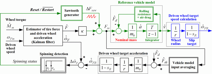
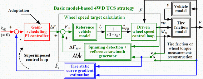
In order to adopt the existing driven wheel speed control loop for 4WD TCS or ABS applications (non-driven wheel speed measurement is not available), the vehicle velocity can be estimated by utilizing an appropriate vehicle model, as shown in Fig. 4. The reference vehicle model, which includes known rolling resistance and air drag loads (cf. Fig. 1), is used to calculate the wheel speed target ωFR. It is fed by the maximum tire traction force Fin, which is estimated by applying a sawtooth-like signal ΔFsaw to the reference model until the driven wheel starts to spin. Wheel spinning is detected when the wheel acceleration excess  becomes larger than a predefined spinning threshold. The sawtooth signal is then reset, and a new cycle is started only after wheel acceleration excess
  falls to small values (which indicates that wheel spinning has ceased).
In order to improve robustness of the overall model-based TCS strategy to vehicle modeling errors (e.g. road slope error or vehicle mass error), the TCS strategy has been extended by a superimposed loop of tire static curve gradient estimation (based on driven wheel measurements only), as shown in Fig. 5. The aim of the superimposed PI controller is to correct the reference model force target Fin in such a way to maintain the driven wheel operation at the desired value of static curve gradient kt = ∂F/∂s ≈ 0 (Fig. 2).
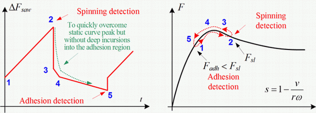
Alternatively, a bi-directional sawtooth-like tire force input signal has been applied to the model-based TCS strategy in Fig. 4, in order to periodically switch the tire force between the spinning and adhesion operating modes, as illustrated in Fig. 6. This is done by first provoking short-term spinning by means of ramping up the tire force input (stages 1-2 in Fig. 6), followed by returning the tire force to the adhesion region (by re-setting and ramping down the tire force input, stages 3-5 in Fig. 6).
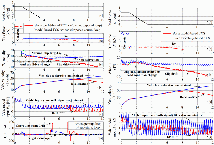
The proposed model-based traction control strategies have been verified by means of simulations by utilizing the longitudinal vehicle dynamics model from Fig. 1. The tire model includes longitudinal tire friction dynamics, and also the tire sidewall compliance. The road noise is also included. The comparative simulation results for the case of simultaneous road condition and road slope changes are shown in Fig. 7. The basic model-based TCS strategy is characterized by a notable wheel slip drift from the desired slip value and vehicle deceleration effects caused by the road slope change. If the superimposed gradient PI controller is applied (Fig. 7a), it reacts to gradient parameter drift from its target value, corrects the target force value Fin of the reference vehicle model, and keeps the wheel slip values close to the target value of 10%. The tire force switching-based TCS strategy provides a very quick reaction to road slope disturbance effect, but the slip/force perturbations are larger than for the gradient control system (Fig. 7b).
a) Utilization of superimposed gradient control loop b) Force switching-based TCS strategy extension
Publications
-
Vehicle System Dynamics, Vol. 49, No. 8, pp. 1245-1265, 2011. -
A Switching Traction Control Strategy Based on Tire Force Feedback
Proc. of 2009 IEEE Multi-conference on Systems and Control, St. Petersburg, Russia, 2009. -
Estimation of Tire Static Curve Gradient and Related Model-based Traction Control Application
Proc. of 2009 IEEE Multi-conference on Systems and Control, St. Petersburg, Russia, 2009. -
A Model-Based Traction Control Strategy Non-Reliant On Wheel Slip Information
21st International Symposium on Dynamics of Vehicles on Roads and Tracks (IAVSD, 2009. -
Traction Control Using Dynamic Tire Friction Potential [open access]
US patent No. US20070213912A1, 2007. -
State Estimation of Automotive Drive with Control Applications [open access]
Doctoral thesis (in Croatian), Faculty of Mechanical Engineering and Naval Architecture, University of Zagreb, Croatia, 2007. -
An In-Wheel Motor-Based Tyre Test Vehicle
International Journal of Vehicle System Modelling and Testing, Vol. 2, No. 3, pp. 252-275, 2007.