Yaw Rate Estimation
The vehicle body yaw rate is essential information needed for vehicle dynamics control systems implementation. Traditionally, the yaw rate is measured by using a gyroscope sensor placed in the vehicle center of gravity (CoG). For the purpose of gyroscope fault diagnosis or cost reduction, the yaw rate can also be estimated by using other vehicle dynamics sensors and an appropriate vehicle model. For instance, the yaw rate can be obtained based on the measurements of two linear accelerometers or based on the measurements of non-driven wheels speed sensors.
For the implementation of kinematic yaw rate estimator using two accelerometers, the diagonal sensor placement configuration has been proposed (see Fig. 1) as a good trade-off between longitudinal and lateral configurations (the longitudinal configuration does not provide the steady-state yaw rate estimate and is prone to drift, while the lateral configuration has low accuracy for low yaw rates and cannot reconstruct the yaw rate sign). By combining kinematic expressions for accelerometers measurements ayf and ayr for the diagonal configuration, the following equation is obtained:
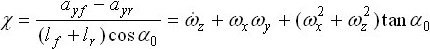
where χ is the accelerometer measurements term. The yaw rate estimator equation is obtained from the above expression after neglecting the small roll ωx and pitch ωy terms:
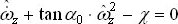
This estimator enables simultaneous estimation of the yaw rate and yaw acceleration. Assuming that the accelerometers are well aligned, the main issue is still a drift-like yaw rate estimation error related to the accelerometers measurement offset and the integration process needed to obtain  .
.
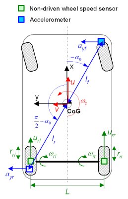
The yaw rate estimator based on the non-driven rear wheels speed sensors for a FWD vehicle has been considered, as well. The yaw rate can be obtained from the non-driven rear wheel speeds (Fig. 1) by using the following kinematic equation:
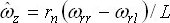
where the unknown tire effective radii rrr and rrl are replaced by the nominal tire radius rn.
This estimation approach cannot be used during braking and road bump disturbances, because large longitudinal tire slips during braking and wheel speed signal spikes due to road bumps cause substantial estimation errors. The estimation accuracy is also affected by the variations of the rear wheels tires effective radii rrr and rrl with respect to their nominal value rn. These radii variations and corresponding yaw rate estimation errors are caused by a single tire deflation or wear, or by a lateral load transfer related to the vehicle roll motion and/or to the road bank angle. These errors, unlike the errors related to braking and road disturbances, can be significantly decreased by utilizing simple vehicle model-based compensation routines.
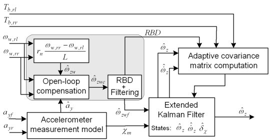
The sensor fusion concept combines the accelerometers and wheel speed sensors measurements, in order to overcome the restrictions upon the estimation accuracy of the individual approaches. The sensor fusion is realized through an adaptive Extended Kalman Filter (EKF), as illustrated in Fig. 2. The combined accelerometer measurement χm and the wheel speed sensor-based estimate  are used as the input signals to the Kalman filter. The signal
  is obtained from the raw pre-estimate
  by compensating for effective tire radii variation-related estimation errors. This signal is then inputted to the RBD block which detects the road bump disturbance by monitoring the variance of the yaw rate pre-estimate. In order to benefit from RBD detection algorithm, a time-delayed filtered copy of the corrected pre-estimate
  is applied to the Kalman filter input.
Within the Kalman filter, the yaw rate, yaw acceleration, and accelerometers measurement offset ( ,
,  , and
, and  ) are defined as state variables. The EKF adaptation is implemented by updating the adaptation covariance matrix, depending on the confidence levels for each individual estimator. The estimator adaptation relies on the braking and road bump detection Boolean statuses, and magnitudes of the yaw rate and yaw acceleration estimates. The accelerometer approach is predominantly used for dynamic yaw rate conditions, during braking maneuvers, and in the presence of road bump disturbances, while the wheel speed sensor approach is activated for quasi-steady-state yaw rate intervals in order to estimate the combined accelerometer offset
  and compensate for the related accelerometer drift-like error.
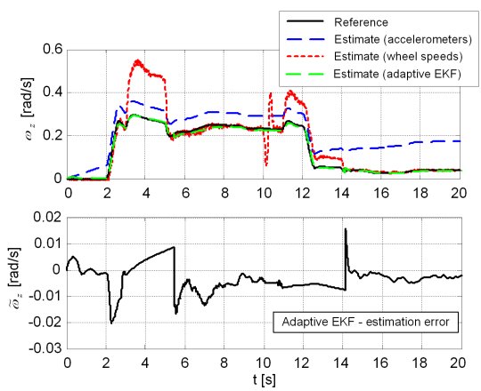
The adaptive EKF-based yaw rate estimator has been verified by comparing the estimated yaw rate signal with the reference obtained from a 10DOF vehicle dynamics model (Fig. 3). In the considered cornering maneuver, the braking torque of 300 Nm per wheel is applied in the time intervals 3-5s and 11-14s, and the road bump disturbance is applied at t = 10s. The wheel speed sensors-based approach has large estimation errors during braking periods and road bump disturbances, while accelerometer approach has significant drift-like error, particularly at low yaw rates (Fig. 3). By using the adaptive EKF-based estimator, all dominant estimation errors are significantly reduced. The remaining errors are mostly well within 10% of the reference value.
More details on analysis of individual kinematic estimators and development of the combined EKF-based estimator are given in our papers listed below.
Publications
-
21st International Symposium on Dynamics of Vehicles on Roads and Tracks (IAVSD, 2009. -
Adaptive Kalman Filter-based Yaw Rate Estimation Using Accelerometers and Wheel Speed Sensors
ASME Dynamic Systems and Control Conference (2009 DSCC), Hollywood, CA, 2009. -
Analysis of Accelerometer-based Kinematic Yaw Rate Estimators
Proc. of 9th International Symposium on Advanced Vehicle Control (2008 AVEC), Kobe, Japan, 2008.