Hydrostatic transmission
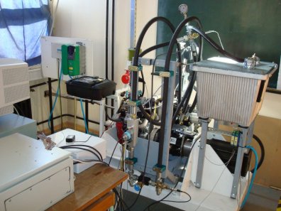
The hydrostatic transmission setup has been designed on the basis of previously developed 14 HP/4000rpm V2 spark-ignition engine setup. A principal scheme of the hydrostatic transmission setup and its photograph are shown below.
The variable displacement hydraulic pump (1) supplies the hydraulic motor (2). The pump and motor are of the axial piston type and the swash plate design, and their maximum displacements are 25 cm3/rev and 35 cm3/rev, respectively, while the maximum pressure is 350 bar. The pump displacement is adjusted by a geared DC servo-motor (6), as a swash plate actuator. The swash plate position is measured by an incremental encoder (14). The hydraulic motor displacement is adjusted manually by a bolt and nut mechanism, and fixed to a desired value. The fluid state sensors include bidirectional flow meter (8) placed in one working hydraulic line, pressure gauges (9) and (10); fluid temperature sensor (11) placed in one line, and return-line fluid temperature sensor.
The engine (3) propels the pump through the selective pulley and belt transmission. Two manually adjusted transmission ratios (1:1 and 2.73:1) are implemented, in order to extend the relatively narrow engine torque/speed operating range towards the larger hydrostatic transmission operating range. The IC engine is controlled by an electronic throttle unit (7). The engine speed is calculated from the pump speed which is measured by incremental encoder (12). The engine torque (i.e. the pump driving torque) is estimated from the mean value engine dynamics model based on the throttle angle and engine speed measurements.
A permanent-magnet synchronous servo-motor (5) serves as a hydraulic motor loading machine (a dynamometer). The servo-motor is also utilized to startup the engine via the hydrostatic transmission. The servo-motor provides an accurate and fast torque control (the torque response time is 2 ms). Thus, the servo-motor torque reference is taken as the actual servo-motor torque (torque measurement is avoided). The servo-motor speed, which is equal to the hydraulic motor speed, is measured by incremental encoder (13).
A Pentium III industrial PC is used to control and monitor the overall experimental setup. The control code, written in C, includes the digital closed-loop controllers of engine throttle angle (a PID controller), swash plate position (a cascade current/speed/position controller), and load servo-motor speed (PI controller).
Fig. 1. Principal scheme of hydrostatic transmission experimental setup.
Publications
-
DVD Proc. of 2008 ASME International Mechanical Engineering Congress and Exposition (IMECE 2008), Boston, MA, 2008.