Wet clutch
The wet clutch experimental setup has been developed with the aim to support a detailed wet clutch modeling work, including thermal and fluid film squeeze effects. The setup is based on the Active Limited Slip Differential hardware. In order to provide space for placement of additional sensors, the experimental wet clutch includes only a single friction plate placed between two separator plates. The additional sensors include separator plate temperature thermocouple, press plate position sensor, and clutch pack axial force sensor.
In order to facilitate the above measurements without using telemetry, the setup has been developed according to the concept shown in the principal scheme below. The driving servomotor is connected to the output differential shaft that carries clutch friction plates. The clutch torque is transmitted through the separator plates to the differential case, which is fixed to the torque measuring system. The bevel gears are removed from the differential case to reduce friction losses.
Photographs of the implemented wet clutch setup and related 3D CAD models are shown below. The setup is driven by the same 120rpm/880Nm/2ms direct drive servo motor (1), as used in the Experimental vehicle and Active differential test rig. The standard half shaft (3) is utilized to connect the motor and the wet clutch input shaft. The output shaft (8) is attached to the differential case (5) via the output gear (7) which is fixed to the case (5) by means of nine radial bolts (6). The output shaft (8) is connected to the torque measuring system, which consists of a 350 mm long lever (9) and a force sensor (10). The torque measuring system force sensor is of strain gauge type with the accuracy class of 0.05% and the nominal force of 500 N.
The press plate position is measured by an LVDT displacement sensor (23, 26) with the measurement range of ±1.25 mm and the measuring resolution of 0.5 μm. The sensor body (23) is fixed to the differential case. The moving part of the sensor, the metal core (26), is connected to the press plate (13) through a fixing plate (14) and a holder (25). The fixing plate is connected to the press plate by three bolts.
Press plate (13) together with the press plate position sensor fixing plate (14) compresses the clutch pack consisting of one friction disc (17) placed between two separator plates (16 and 18). In order to provide realistic thermal boundary conditions, a "dummy" friction discs (15) is placed in-between the fixing plate (14) and the separator plate (16), and another "dummy" friction disc (19) is glued to the axial force sensor plate (20) on the other side of the clutch pack.
The axial force measurement is based on measuring the reaction force in one of three support points. The separator plate (18) leans to a plate (20) which is attached to the differential case in three points. One of the supporting points is a piezoelectric compression force sensor (21), while the other two supporting points are supporting blocks (22) of the same size and similar axial compliance as those of the sensor. The sensor nominal force is 22 kN with the sensitivity of S = 4047 pC/kN.
The separator plate temperature is measured by a J-type 50μm thermocouple with declared response time of 7 ms in still water. The thermocouple (26) is placed in a 0.5 mm deep slot in the 1.3 mm thick separator plate (18).
The electrical and control system is the same as described for Active differential test rig, except that additional amplifiers and A/D channels are added for additional sensors used.
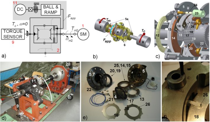
2 - Differential body
3 - Input shaft
4 - Input gear (teeth removed)
5 - Differential case
5a - Differential case bearings
6 - Fixing bolts
7 - Output gear
8 - Output shaft
9 - Torque measuring system lever
10 - Force sensor
11 - Clutch motor DC actuator
12 - Ball and Ramp output plate
13 - Press Plate
14 - Press plate position sensor fixing plate
15 - "Dummy" friction disc 1
16 - Separator plate 1
17 - Friction disc
18 - Separator plate 2 w/ slot for thermocouple
19 - "Dummy" friction disc 2
20 - Axial force sensor plate
21 - Piezo axial force sensor
22 - Supporting block
23 - LVDT (press plate position sensor) body
24 - LVDT (press plate position sensor) metal core
25 - LVDT holder
26 - 50 μm Thermocouple
27 - Sensor amplifiers
28 - Industrial Pentium III PC, electric motor power supply and control subsystem
Fig. 1. Wet clutch setup: (a) principal scheme, (b) 3D wet clutch model, (c) zoom-in detail of clutch explosion view, (d) photograph of setup, (e) photograph of wet clutch components, and (f) photograph of thermocouple detail.
Publications
-
SAE paper #2008-01-0302, 2008 SAE World Congress, Detroit, MI, 2008.