Disc-on-disc tribometer
The disc-on-disc-type CNC tribometer has been developed for the purpose of conducting dry clutch friction coefficient and wear characterization tests over a wide range of operating parameters and different friction materials, and by using an entire friction plate as a sample (as opposed to the pin-on-disc tribometer which employs a sample of friction material).
The non-rotating disc (i.e. the pressure plate, 8) is attached to a source of variable normal/axial force (vertical axis), while the rotating disc (i.e. the friction plate, 9) is placed on a rotating table connected to a source of variable torque (rotational axis). The pressure plate is connected to the vertical axis by utilizing a precise, stiff and compact force and torque piezoelectric sensor (4), thus preventing any parallel (typically friction loss) force/torque transfer paths that would affect the measurement accuracy.
The vertical axis is based on a relatively small-power electric servomotor (1) (2.15 Nm @ 3000 rpm, max. 10 Nm) and a high-ratio screw-drive reducer (2) (1 mm/rev), which transforms the rotational speed/torque of the motor into a translation velocity/force. A torque reaction support system (3) (a linear ball bearing) is incorporated as an integral part of the vertical axis.
A custom-designed leaf spring-based suspension system (6) of the vertical axis is designed to ensure a uniform contact between sliding surfaces and provide torque transfer from the pressure plate (8) and the water-cooling disc (7) towards the normal force/torque sensor (4) via a thermal insulation disc (5). In order to protect the torque sensor (and overall machine) from vibration-caused transient overloads during experiments with shudder sensitive friction materials, the machine can be equipped with a set of four dampers installed between the cooling disc and the housing. The dampers are arranged in two opposing pairs attached on the opposite side of the cooling disc and placed in the horizontal plane, and they are connected to the housing via rotary joints.
The friction interface temperature is measured by a Pt100 sensor probe installed into the pressure plate (8). The bore made for accommodating the temperature sensor is placed at 4 mm axial distance from the friction contact surface and at the effective radius of the pressure plate.
The rotational axis is based on a high-power servomotor (14) (110 Nm @ 3000 rpm, max. 270 Nm), which powers the rotating table (10) over a servo coupling (13) and the main shaft (12). Proper torque transfer from the main shaft onto the friction plate is achieved over a cut portion of the corresponding transmission input shaft. The excessive heat generated in the friction plate (9) is prevented from reaching the bearing system by means of a water-cooled rotary table (10) and a thermal insulation material-based plate (11). The coolant intake and outtake ports are designed as a custom rotary joint based on dynamic seals. Cooling fluid transfers the friction-dissipated heat towards a cooling unit (6 kW of cooling power), where the fluid is cooled down by a heat exchanger through air cooling. Particles and odor from the tribometer chamber are removed by utilizing an industrial ventilation system (1100 m3/hr) equipped with adequate filters.
Since disc-on-disc tribometer resembles the friction contact conditions occurring on the actual clutch, the wear tests have been conducted in a more realistic scenario than on pin-on-disc tribometer i.e. as a series of clutch closing cycles. Each test cycle consists of the following phases (see the illustration below):
- 1) ramping up the slip speed to the target level under idling operation (no clutch friction load),
- 2) bottoming the vertical axis,
- 3) ramping up the normal force (interval t1),
- 4) keeping the normal force at the target level Fz2 until the slip speed drops to zero (interval t2), and
- 5) lifting up the vertical axis and imposing a pause needed to control the friction interface temperature at the target level (interval td).
The torque (or normal force), slip speed, friction interface temperature, and closing time are accurately controlled during tests by employing rotational- and vertical-axis servodrives and the water-cooling system. The disc temperature is controlled by means of imposing a delay between two consecutive clutch closing cycles, varying the cooling pump speed, and manipulating an on/off valve that can bypass the coolant flow around the pressure plate. The friction interface torque control system is realized in a cascade structure including inner normal force and vertical axis speed controllers. The closing time is controlled by means of “electrical inertia” implemented through rotational-axis servomotor torque control.
-
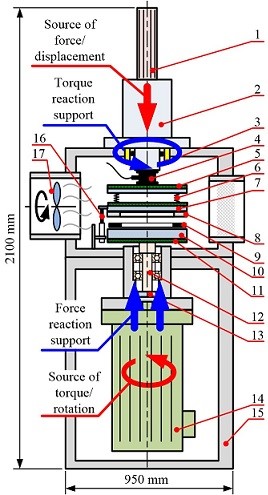
- 1. Vertical (linear) axis motor
- 2. Linear axis reducer (screw drive)
- 3. Torque reaction guide
- 4. Normal force / torque sensor
- 5. Thermal insulation plate
- 6. Suspension systems
- 7. Water cooling disc
- 8. Pressure plate
- 9. Friction plate
- 10. Rotating table
- 11. Thermal insulation plate
- 12. Main shaft
- 13. Motor coupling
- 14. Rotational axis motor
- 15. Housing
- 16. LVDT sensor
- 17. Ventilation system
Fig. 1. Functional schematic of designed disc-on-disc tribometer machine. -
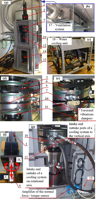
Fig. 2. Photographs of disc-on-disc tribometer.
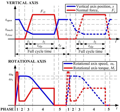
Fig. 3. Qualitative representation of test cycle.
Publications
-
Machines, Vol. 12, No. 1, pp. 25, 2024. -
Experimental Characterization and Modeling of Automotive Dry Clutch Friction Lining Wear
Kupplungen und Kupplungssysteme in Antrieben 2019, Ettlingen bei Karlsruhe, Germany, 2019.