Modeling of Magnetorheological Fluid Clutch
The magnetorheological fluid (MRF) devices such as dampers and clutches have drawn some significant research and development interest for last 15 years. The main advantages of these devices compared to their electrohydraulical or electromechanical counterparts are simplicity of design and excellent controllability. The main automotive applications include semi-active suspension dampers, and clutches used in auxiliary engine devices, steer-by-wire systems, and active differentials.
For the experimental MRF clutch, a semi-empirical mathematical model has been proposed and experimentally validated. Fig. 1 depicts the overall structure of the MRF clutch model.
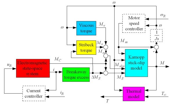
Fig. 1. Principal block diagram of overall MRF clutch model.
Electromagnetic state-space system is the core of the model. This system is based on the equivalent transformer-like first-order model of solenoid and eddy current dynamics (Fig. 2), which is extended by the hysteresis effect illustrated in Fig. 3. The overall electromagnetic circuit model has a compact second-order physical form:
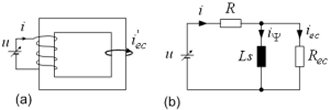
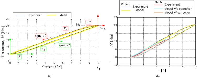
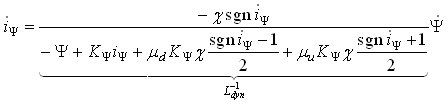
where the first and third equations describe the solenoid and eddy current dynamics, and the second equation accounts for the magnetic hysteresis memory. The empirical factors μu and μd are used to model the effect of narrowing hysteresis, as illustrated in Fig. 3b.
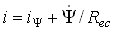
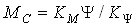
The net (yield) torque MC obtained from Electromagnetic state-space system is added to the Stribeck+viscous torque component Msv to obtain the total clutch sliding torque Mslip. The Stribeck component Ms of the torque Msv is obtained from a look-up table based on the averaged breakaway test results. The Viscous torque component Mv is calculated based on interpolation of the averaged torque vs. speed test curves after referring them to zero-current operating condition (by subtracting the net torque). The interpolation is linear for |ω| ≥ 100 rpm and linear in logω scale for |ω| < 100 rpm. The sliding torque Mslip and the driving motor torque Mm (applied torque) are fed to the Karnopp stick-slip model to obtain the total clutch torque.
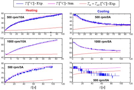
Thermal model is based on the heat balance equation CdT/dt = Mω - H(T - T∞), where the measured solenoid temperature Tsol can conveniently be used as the 'environmental' temperature T . Unlike the wet clutch , which is characterized by a complex time-varying heat transfer factor H, the MRF clutch is found to have an approximately constant factor H. Except for the monitoring purposes, the predicted MRF temperature may be used to correct the Viscous torque model.
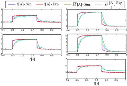
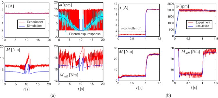
For the purpose of experimental validation, the MRF clutch model in Fig. 1 is extended by actual Current controller and Motor speed controller modules. The experimental validation results are shown in Figs. 4-6. The clutch current and normalized torque responses in Fig. 4 indicate a good accuracy of electromagnetic circuit model. It should be noted that the torque response is delayed with respect to current response due to the eddy current effect. Accuracy of the thermal model is illustrated in Fig. 5. A good prediction of stick-slip and high-speed (viscous) clutch torques is demonstrated in Fig. 6.
More details on MRF clutch experimental characterization, modeling, and validation are given in the publications listed below.
Publications
-
Strojarstvo, Vol. 52, No. 6, pp. 689-702, 2010. -
Design and Experimental Characterization of a Magnetorheological Fluid Clutch
SAE paper #2009-01-0142, 2009 SAE World Congress, Detroit, MI, 2009. -
Modeling of Electromagnetic Circuit of a Magnetorheological Fluid Clutch
Proc. of 2009 IEEE Multi-conference on Systems and Control, St. Petersburg, Russia, 2009.