Modeling of Active Differential Dynamics
Active differentials provide a controlled left/right or front/rear torque distribution to the wheels, thus enhancing the traction control and yaw rate control performances without being intrusive for the driver. The active differentials can be divided in two main groups: (i) Active Limited Slip Differentials (ALSD) and (ii) Torque Vectoring Differentials (TVD). For the purpose of vehicle dynamics control system design and simulation, a unified mathematical/simulation model of driveline dynamics for various active differential types has been developed and analyzed.
Fig. 1 shows the kinematic schemes of four common types of active differentials. The ALSD (Fig. 1a) includes a clutch that connects the rotating differential case with one of the output shafts. Since the clutch torque transfer is always directed from the faster to slower clutch shaft and the case speed is equal to the average left/right wheel speed, the ALSD always transfers the torque from faster to slower wheel. The TVDs (Figs. 1b-1d) comprise two clutches and additional gearing, in order to provide the torque transfer to both slower and faster wheel. The allowable wheel speed difference for the torque transfer to faster wheel is determined by the additional-gearing equivalent speed ratio, and is typically in the range from 10% to 25%. The clutches can be of superposition type (Fig. 1b) or stationary type (Fig. 1c,d). The 4WD TVD in Fig. 1d is used as an active rear differential along with the passive (open) front differential, where the two differentials are connected through a speed increasing device in the TVD mode.
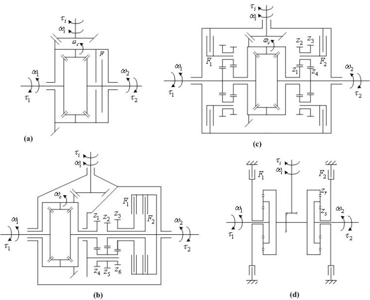
Fig. 2 shows the bond graph models of driveline dynamics for the above active differentials.
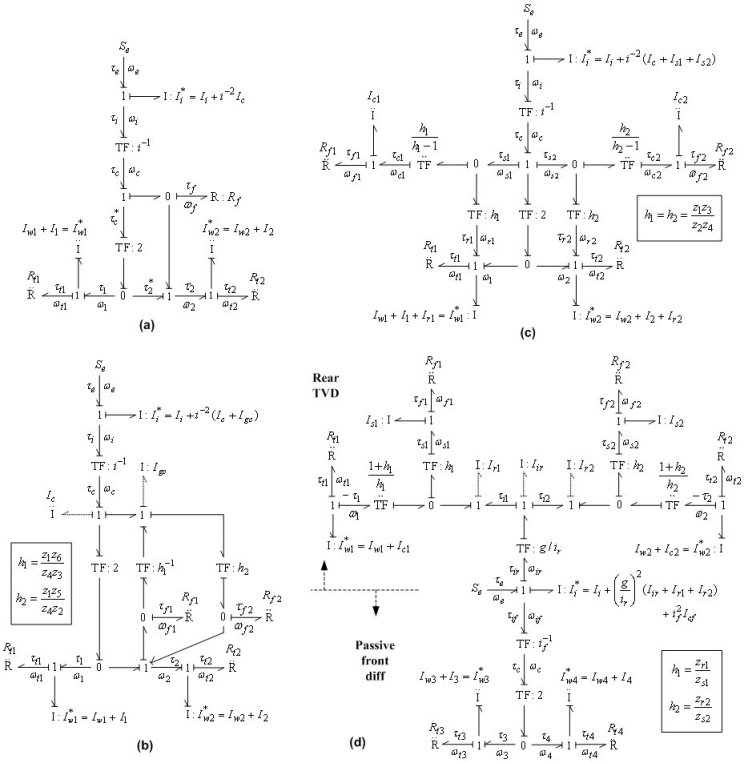
By setting the torque-output causality for the tire and clutch friction resistance elements Rti (i = 1,2 or i = 1,...4) and Rf1,2, respectively, and integral causality for the wheel inertia Iwi*, it turns out that the input inertia Ii* (and other inertia if applicable) is of derivative causality. Therefore, the overall model is of second-order for 2WD driveline and fourth-order for 4WD driveline, and it is given by the following unified set of equations:


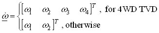

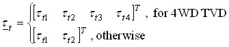
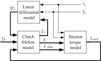
and where the inertia matrix A, the input matrix B, and speed transformation matrix F depend on the differential type. Numerical integration of the above state-space equation gives the wheel speed vector ω, which is then algebraically transformed to the clutch speed vector ωf. The clutch speed vector ωf and the demanded clutch torque vector τh are used to calculate the clutch friction torque vector τf, which is fed back together with the input torque τe and the tire load torque vector τt to the linear state-space model. Fig. 3 depicts the model implementation based on the Karnopp model for clutch friction. Linear differential model is given by the above equations. Clutch friction model is based on the generalized Stribeck static friction curve and the applied torques to the clutch elements τstick calculated by the block Stiction torque model. The model can easily be extended by halfshaft compliance and differential inertia effects.
The developed model has been used as a basis for comparative algebraic and simulation analyses of active differential driveline dynamics. The drivability analysis has shown that the shuffle vibration mode features (the mode excited by the input torque) are comparable for all differentials. On the other hand, another vibration mode excited by the clutch torque may have unfavorable low-frequency features for the TVD with stationary clutches, because the clutch and gear inertia can become relatively large when referred to the differential output shaft via a large equivalent gear ratio. The time response analysis has pointed out that, besides the disadvantage of transfering the torque to the slower wheel only, the ALSD suffers from a slow and/or steady-state inaccurate torque transfer response for very small wheel speed differences.
More detailed information on model development for different driveline configurations, steady-state and transient analyses, and simulation results is included in the publications listed below.
Publications
-
ASME Journal of Dynamic Systems, Measurement, and Control, Vol. 132, No. 6, pp. 061501/1-13, 2010. -
Bond Graph Modeling of Automotive Transmissions and Drivelines
Proc. of 7th Vienna International Conference on Mathematical Modelling (MATHMOD), Vienna, Austria, 2012. -
A Closed-Loop Strategy of Active Differential Clutch Control
ASME Dynamic Systems and Control Conference (2009 DSCC), Hollywood, CA, 2009. -
Modelling and Analysis of Torque Vectoring Differential Kinematics
Proc. of the 6th International Congress of Croatian Society of Mechanics, Dubrovnik, Croatia, 2009. -
Bond Graph Modeling and Analysis of Active Differential Kinematics
2008 ASME Dynamic Systems and Control Conference, Ann Arbor, MI, 2008. -
Experimental Setups for Active Limited Slip Differential Dynamics Research
SAE paper #2008-01-0302, 2008 SAE World Congress, Detroit, MI, 2008. -
Modeling of Active Differential Dynamics
DVD Proc. of 2008 ASME International Mechanical Engineering Congress and Exposition (IMECE 2008), Boston, MA, 2008. -
A Control-oriented Model of Hydrostatic Transmission with Application on Torque Vectoring Differential Modeling
DVD Proc. of 2008 ASME International Mechanical Engineering Congress and Exposition (IMECE 2008), Boston, MA, 2008. -
Clutch Actuation
Encyclopedia of Automotive Engineering, pp. 1-19, John Wiley & Sons Ltd., 2014.