Dry dual clutch transmission
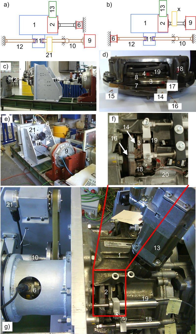
Transmission setup (1), given in Configuration 1 (Figs. a, c, e, g), is suitable for characterization of torque transfer and thermal dynamics phenomena of the clutch (2), where the direct measurements of clutch torque, press plate positions, and clutch friction interface temperatures are required. This is provided by grounding the flywheel (3) and the associate press plates (4,5) by means of a strain-gauge reactive torque sensor (6). On the other hand, the friction plates (7,8) are driven from the wheel side by a high-torque servomotor (9) through one of the half shafts (10), the differential (11), and the transmission gears, while the other half shaft (12) is grounded. The clutch actuator is driven by an AC servomotor (13). The control and monitoring system is built around an industrial PC, and it is adopted from the previously used active differential setup.
J-type iron-constantan thermocouples are placed in four blind holes drilled in the non-rotating flywheel (14, 15) (2 bores) and the press plates (16, 17) (1 bore in each), at the clutch mid radius with 2 mm axial distance from the friction surface. The axial displacements of both press plates (16, 17) are measured by LVDT displacement sensors (18, 19). Additionally, engagement bearing displacements are measured using custom built contactless sensors installed within bell housing. The clutch bell housing temperature is sensed by self-adhesive thermocouples (20). The clutch slip speed is measured by using a high-resolution incremental encoder (21) placed at the differential input. Also, the built-in low-resolution transmission speed sensors can be used to provide direct measurements of transmission input and output shafts.
Configuration 2 of the test rig (see Fig b) is aimed to overcome the main shortcoming of Configuration 1 regarding the reverse power transmission over a single half shaft (e.g. unrealistic load may cause differential pinion gears to wear out quickly). This configuration is, thus, suitable for various long-duration tests (e.g. wear tests) and realistic shuffle mode and control tests, but the temperature and press plate measurement are not possible, and the clutch torque sensing is less direct. The flywheel (3) is directly driven by using the same high-torque electric servomotor (9). Both half shafts (10, 12) are grounded, one of which by the reactive torque sensor (6) used in Configuration 1 to ground the flywheel. In addition, the half shaft torques can be measured by a custom-made system of strain-gauges (22) glued to the half shafts.

2. Clutch
3. Clutch flywheel
4., 5. Clutch press plates
6. Clutch torque sensor
7., 8. Clutch friction plates
9. High-torque driving servomotor
10., 12. Half shafts
11. Differential
13. Actuator servomotor
14., 15. Flywheel thermocouples
16., 17. Press plates thermocouples
18., 19. LVDT sensors of press plate displacement
20. Clutch housing self-adhesive thermocouples
21. Transmission encoder
22. Strain-gauge sensors of half shaft torque
Fig. 1. Schematics and photographs of test rig of dry dual clutch transmission in Configuration 1 (a, c, e, f, g) and Configuration 2 (b), and related dry dual clutch (d).
Video 1. Short video presentation of a typical experiment in Configuration 1.
Video 2. Short video presentation of a typical experiment in Configuration 2.
Publications
-
Proceedings of the Institution of Mechanical Engineers, Part D: Journal of Automobile Engineering, Vol. 232, No. 2, pp. 161–174, 2017. -
Experimental Characterization of Dry Dual Clutch Elastic Components with Application to Clutch Modelling
Powertrain Modelling and Control Conference (PMC2014), Bradford, UK, 2014. -
Experimental Characterization and Modeling of Dry Dual Clutch Wear
SAE paper #2014-01-1773, SAE International Journal of Passenger Cars - Mechanical Systems, Vol. 7, No. 1, pp. 326-337, 2014. -
Experimental Characterization and Modeling of Dry Dual Clutch Thermal Expansion Effects
SAE paper #2013-01-0818, SAE International Journal of Passenger Cars - Mechanical Systems, Vol. 6, No. 2, pp. 775-785, 2013. -
Design of Test Rigs for a Dry Dual Clutch and its Electromechanical Actuator
SAE paper #2012-01-0807, SAE International Journal of Passenger Cars - Mechanical Systems, Vol. 5, No. 1, pp. 612-620, 2012.